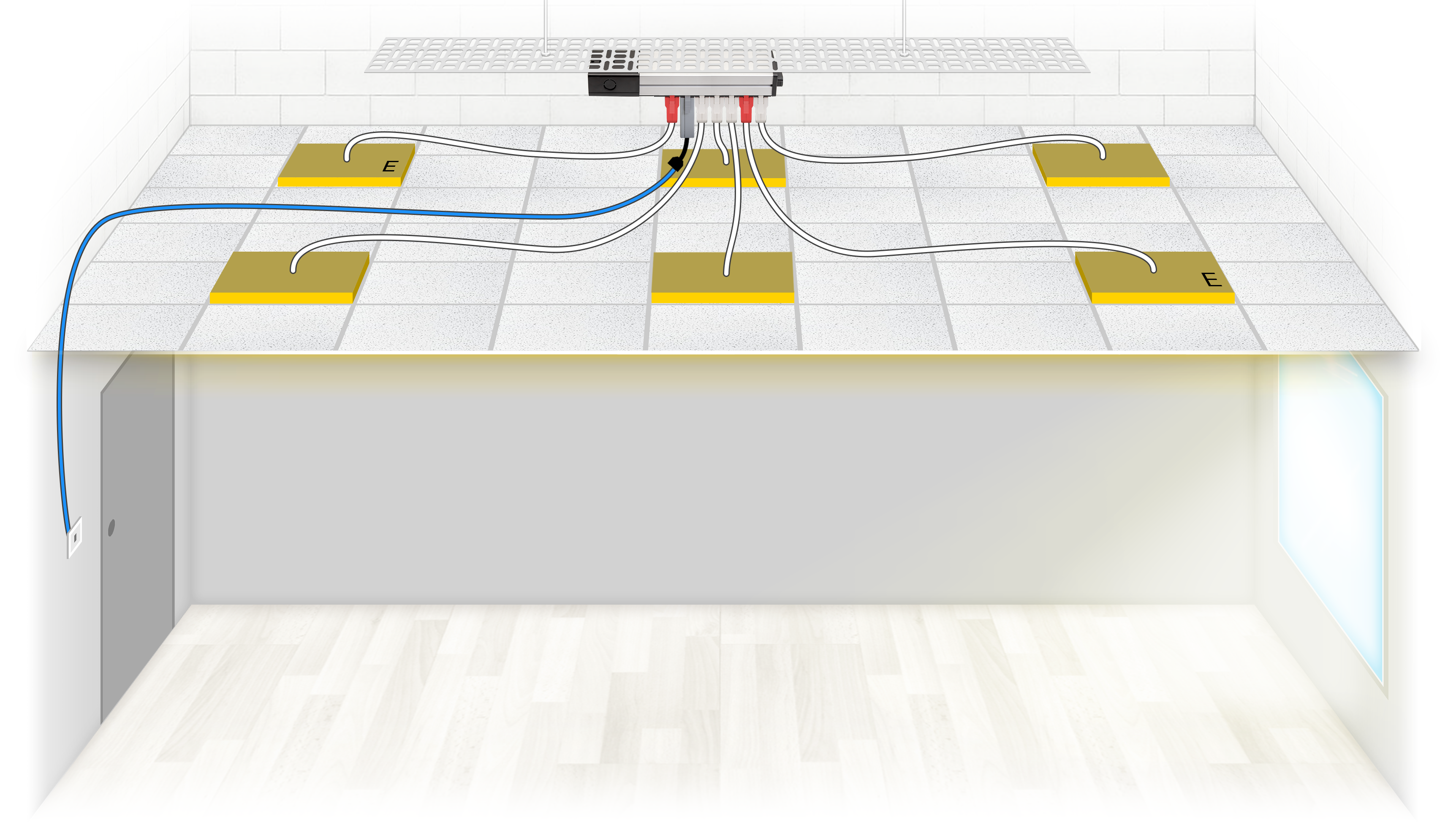
flex7 Applications – PELV Switching


| DESCRIPTION | PART NO. |
|---|---|
| 1 X Starter Distribution Box | FSU08 |
| 1 X Switch Kit | FNS1000/U |
| 1 X Switch | FWS01/K/AT/W/WP |
| 1 X Switch Adaptor | FWSY/13/AT |
| 4 X Standard (on/off) Luminaire Leads | FL3100LSHF5/W |
| 2 X Maintained Emergency Luminaire Leads | FL4100LSHF5/R |
Control of the luminaires is from 1 location via a flex7 plug-in switch operating at PELV. The luminaires are manually switched on or off with a short pulse of the switch.
The use of flex7 control modules negate the need for RCD and/or earthed mechanical protection of the switch drop.
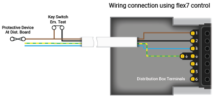
Additionally, installation time is dramatically reduced as everything plugs-in, meaning only the 4 conductors at the Distribution Box require on-site termination.
Note: emergency luminaires are tested via a hard-wired 230V key switch, often located in close proximity to the distribution board.
 | Call Us: +44 (0)20 8580 1066 | sales@flex7.co.uk