flex7 Applications – PELV Switching & Manual Dimming


| DESCRIPTION | PART NO. |
|---|---|
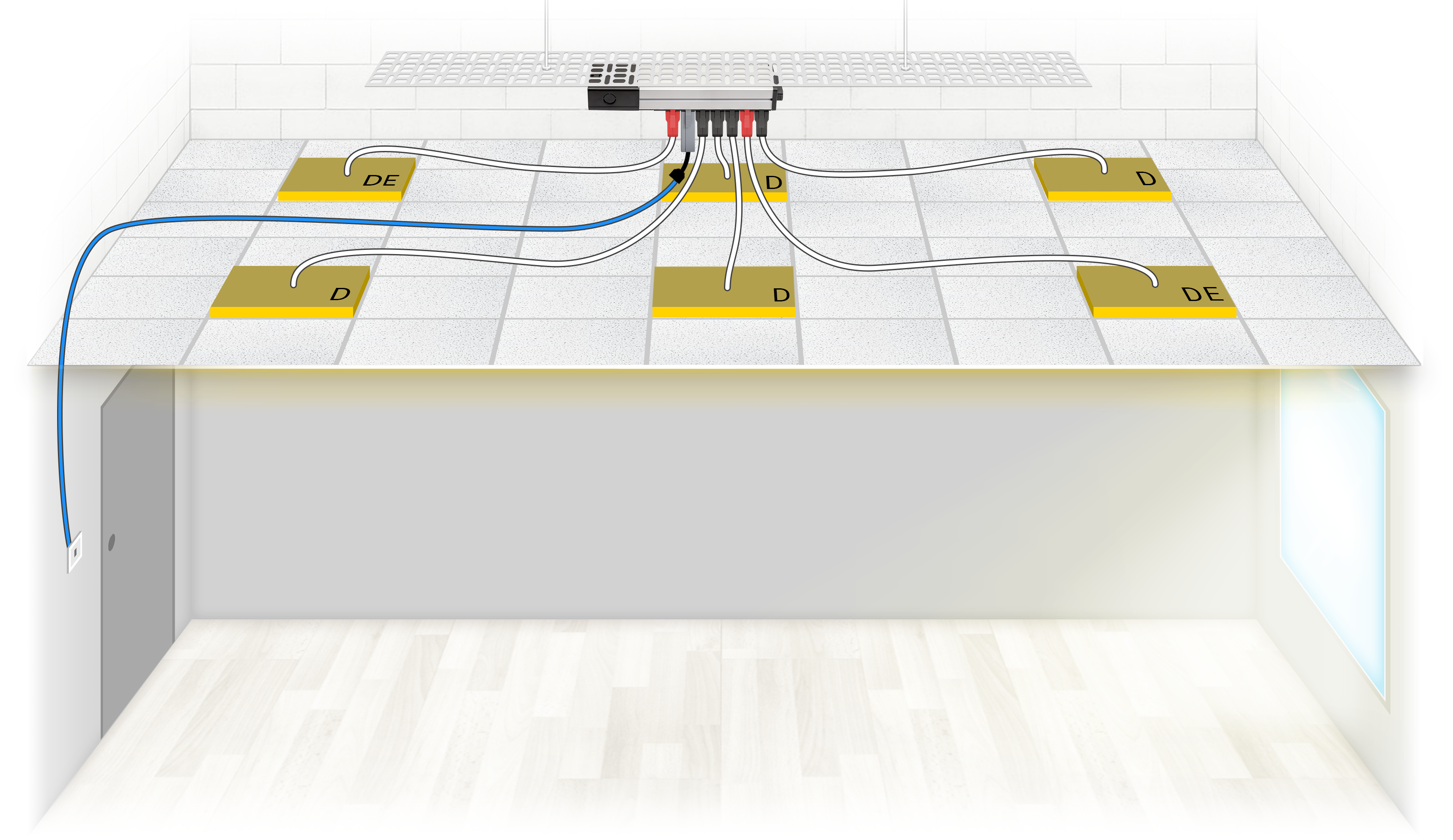
| 1 X Starter Distribution Box | FSU08 |
| 1 X Switch Kit | FNS3000X/U |
| 1 X Switch | FWS01/K/AB/W/WP |
| 1 X Switch Adaptor | FWSY3/AB |
| 4 X Dimming Luminaire Leads | FL5100LSHF5/B |
| 2 X Dimming Maintained Emergency Luminaire Leads | FL6100LSHF5/R |
Control of the luminaires, both switching and manual dimming, is from 1 location via a flex7 plug-in switch operating at PELV. The luminaires are manually switched on or off with a short pulse of the switch. Once on, the luminaires can be dimmed or brightened by holding the switch until the desired light level is reached.
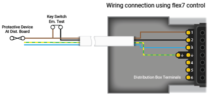
The use of flex7 control modules negate the need for RCD and/or earthed mechanical protection of the switch drop. Additionally, installation time is dramatically reduced as everything plugs in meaning only the 4 conductors at the Distribution Box require on-site termination.
Note: emergency luminaires are tested via a hard-wired 230V key switch, often located in close proximity to the distribution board.
 | Call Us: +44 (0)20 8580 1066 | sales@flex7.co.uk